- 您现在的位置:买卖IC网 > Sheet目录318 > CAT3661HV3-GT2 (ON Semiconductor)IC LED DRVR WHT BCKLGHT 16TQFN
�� �
�
�CAT3661�
�range.� Extra� external� resistors� can� be� added� to� the� top� or�
�bottom� of� the� internal� resistor� divider� network� to� alter� the�
�divider� ratio� gain� factor.� The� low� battery� indicator� trip� point�
�can� be� calculated� by� the� following� formula:�
�V� LB� +� V� ADJ� G� ADJ�
�V� LB� =� Low� Battery� Voltage� Trip� Point�
�V� ADJ� =� Low� Battery� Comparator� Trip� point� (0.6� V)�
�G� ADJ� =� Resistor� Divider� Gain� (4� internally)�
�To� obtain� a� low� battery� trip� point� of� 2.4� V,� the� ADJH� pin�
�is� shorted� to� VIN,� and� the� ADJL� pin� is� tied� to� GND.�
�To� increase� the� low� battery� trip� point,� insert� a� resistor�
�between� ADJH� and� VIN.� To� consequently� lower� the� low�
�For� V� LB� >� 2.4� V,� use� R� L� =� 0� W� and�
�R� H� (k� W� )� ?� 200� (V� LB� /0.6� –� 1)� ?� 600�
�For� V� LB� <� 2.4� V,� use� R� H� =� 0� W� and�
�R� L� (k� W� )� ?� 600� (0.6/(V� LB� –� 0.6))� –� 200�
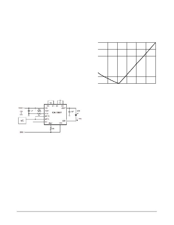
�Figure� 26� shows� the� external� resistor� value� for� low� battery�
�voltage� trip� points� (V� LB� )� between� 2� V� and� 3.2� V.� For� V� LB�
�above� 2.4� V,� R� L� =� 0� W� .� For� V� LB� below� 2.4� V,� R� H� =� 0� W� .�
�240�
�200�
�160�
�battery� trip� point,� insert� a� resistor� between� ADJL� and� GND.�
�The� following� formula� shows� how� to� calculate� the� modified�
�resistor� divider� gain:�
�120�
�80�
�RH�
�G� ADJM� +�
�R� ADJ� )� R� H�
�(R� ADJ� G� ADJ� )� )� R� L�
�40�
�RL�
�G� ADJM� =� Modified� resistor� divider� gain�
�R� ADJ� =� Total� resistance� of� divider� (800� k� W� typ.)�
�R� H� =� High� external� resistor� (ADJH� to� VIN)�
�R� L� =� Low� external� resistor� (ADHL� to� GND)�
�0�
�2.0�
�2.2� 2.4� 2.6� 2.8�
�TRIP� POINT� VOLTAGE� (V)�
�Figure� 26.� V� LB� vs.� R� H� &� R� L�
�3.0�
�3.2�
�The� low� battery� trip� point� does� not� operate� for� adjustments�
�below� 2.0� V� VIN.�
�The� inclusion� of� the� ADJH� pin� allows� monitoring� of�
�supplies� other� than� the� supply� to� the� CAT3661.� Simply�
�connect� ADJH� pin� directly� to� the� supply� to� be� monitored� and�
�the� low� battery� indicator� will� function� as� normal� when� the�
�device� is� enabled.� When� EN� is� low,� no� current� will� flow� in�
�the� resistor� divider� network� allowing� ‘zero’� current�
�shutdown� mode.�
�Under� Voltage� Lockout�
�Figure� 25.� Application� Circuit� with� R� H� &� R� L�
�The� resistance� required� for� a� certain� trip� point� voltage� can�
�be� calculated� by� rearranging� the� above� equations� with�
�respect� to� R� H� or� R� L� .�
�If� the� voltage� on� VIN� is� less� than� V� UVLO� threshold,� the�
�nFLTB� output� is� driven� low� and� the� device� enters� a� low�
�power� state� where� the� LED� output� is� off.�
�When� the� device� is� in� shutdown� (EN� low),� the� nFLTB� pin�
�will� float� high� to� ‘zero’� current� state.�
�http://onsemi.com�
�10�
�发布紧急采购,3分钟左右您将得到回复。
相关PDF资料
CAT37TDI-T2
IC LED DRVR WHITE BCKLGHT TSOT-5
CAT4002ASD-GT3
LED DR 2 CH EZ DIM I/F SC-88
CAT4003BTD-GT3
IC LED DVR 3CH TSOT23-6
CAT4004AHU2-GT3B
IC LED DVR 4CH EZ DIM I/F 8DFN
CAT4004VP2-T3
IC LED DRIVER LINEAR 8-TDFN
CAT4008W-T2
IC LED DRIVER LINEAR 16-SOIC
CAT4101TV-T75
IC LED DRVR HP CONST CURR D2PAK
CAT4104V-GT3
IC LED DVR 4CH 175MA 8SOIC
相关代理商/技术参数
CAT37
制造商:TI 制造商全称:Texas Instruments 功能描述:CMOS White LED Driver Boost Converter
CAT37_05
制造商:CATALYST 制造商全称:Catalyst Semiconductor 功能描述:CMOS White LED Driver Boost Converter
CAT37_08
制造商:TI 制造商全称:Texas Instruments 功能描述:CMOS White LED Driver Boost Converter
CAT37EKK-TE7
制造商:CATALYST 制造商全称:Catalyst Semiconductor 功能描述:CMOS White LED Driver Boost Converter
CAT37RD4-TE13
制造商:CATALYST 制造商全称:Catalyst Semiconductor 功能描述:CMOS White LED Driver Boost Converter
CAT37TDI
制造商:CATALYST 制造商全称:Catalyst Semiconductor 功能描述:CMOS White LED Driver Boost Converter
CAT37TDI-GT3
功能描述:LED照明驱动器 LED Driver Boost 4 LED series RoHS:否 制造商:STMicroelectronics 输入电压:11.5 V to 23 V 工作频率: 最大电源电流:1.7 mA 输出电流: 最大工作温度: 安装风格:SMD/SMT 封装 / 箱体:SO-16N
CAT37TDI-T2
功能描述:IC LED DRVR WHITE BCKLGHT TSOT-5 RoHS:是 类别:集成电路 (IC) >> PMIC - LED 驱动器 系列:- 标准包装:1 系列:- 恒定电流:- 恒定电压:- 拓扑:PWM,切换式电容器(充电泵) 输出数:1 内部驱动器:是 类型 - 主要:背光 类型 - 次要:白色 LED 频率:642kHz 电源电压:2.7 V ~ 5.5 V 输出电压:5V 安装类型:表面贴装 封装/外壳:10-VFDFN 裸露焊盘 供应商设备封装:10-VSON 包装:剪切带 (CT) 工作温度:-30°C ~ 85°C 产品目录页面:1371 (CN2011-ZH PDF) 其它名称:BD1603NUV-E2CT